Version and revision: V1.0 / R0.
For Nethserver 6.7 and above
Skill: intermediate, network
Published: 2016-03-07
Review: 2016-03-07
Author: Ken Isaacs
Contact: @kisaacs
Background
TekSavvy is a Canadian ISP that provides both static IP addresses as well as /30 (or /29) subnets. The problem is that most DSL routers can handle the first but not the second (without a lot of digging/hard work). Nethserver provides a clean standard way to handle both.
When an additional subnet service is provided by TekSavvy, the additional subnet is routed over the static IP. This basically requires the server that handles the static IP to also act as the gateway for the additional subnet.
A /30 subnet provides two usable IP addresses (one of which is allocated to the gateway). A /29 subnet provides six usable IP addresses (one of which is allocated to the gateway).
This how-to addresses each service element in order. First setup the PPPoE and make sure that works, then setup the subnet.
In order to setup PPPoE on Nethserver, you require:
- one allocated ethernet interface for your internal network (e.g. eth0, ens32) and
- one unallocated ethernet interface for your external network (e.g. eth1, ens192).
- Optionally one ethernet interface for your additional subnet service (e.g. eth2, ens224)
In this how-to, the following networks are being setup:
PPPoE (RED) – controlled by the ISP (could be dynamic or static) – does not matter since the PPPoE setup controls that
internal (GREEN) – uses 192.168.32.0/24 (that makes sure that it does not overlap standards used by many ISPs such as 192.168.0.0/24 to 192.168.2.0/24)
external /30 subnet (ORANGE) – 76.10.177.52/30 – provided by the ISP
Make sure that the Nethserver gateway has one ethernet interface plugged into the router and the other into your internal network. In this example, ens32 is internal and ens192 is external. On Nethserver 6.7, you will see eth0, eth1 naming conventions.
Step 1 – set your DSL router into bridge mode
The manner in which you must do so is hardware dependant (and therefore beyond the scope of this how-to). If you are not able to get your router into bridge mode, at the very least, stop it signing on to the network using PPPoE.
What is most important here is that the router no longer signs onto the network using the username/password provided by your ISP. Nethserver will take over that job.
Step 2 – setup your internal interface
Screenshot 1 shows a sample configuration (note that the gateway entry is left blank). Make sure that it is in the GREEN zone

- Screenshot 1
When you click SUBMIT, you should be able to ping any other internal systems.
Step 3 – setup PPPoE
Screenshot 2 shows answers when you add a new interface. Select RED zone and PPPoE, then click NEXT.
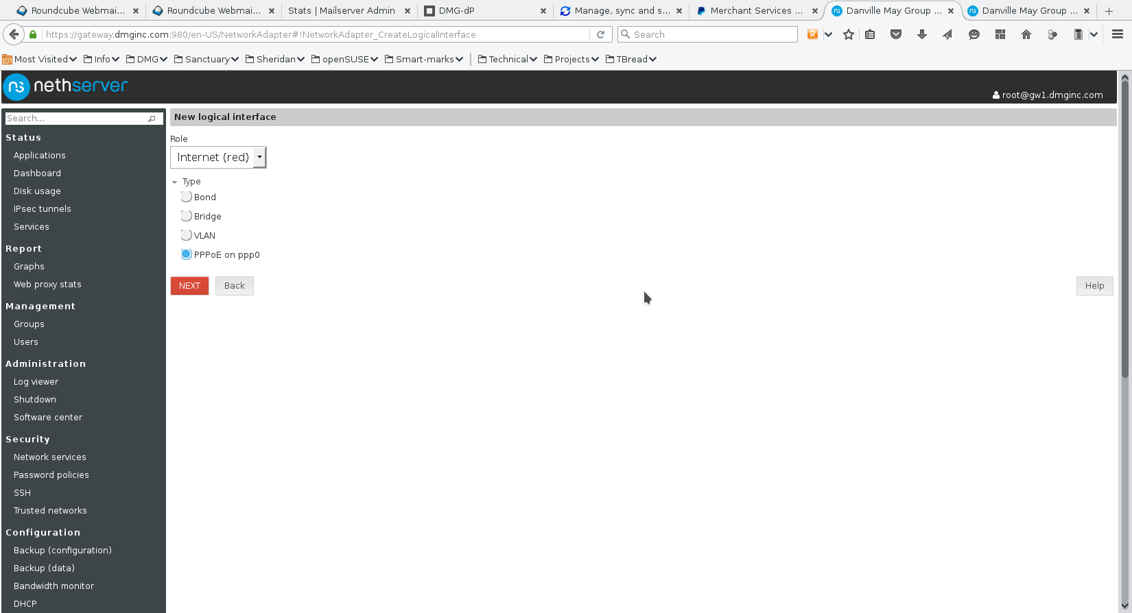
- Screenshot 2
Screenshot 3 shows a sample ppp0 configuration. The key considerations are that you MUST use an unallocated ethernet interface. Normally the pull-down on the Ethernet interface will show you just which one(s) is available.
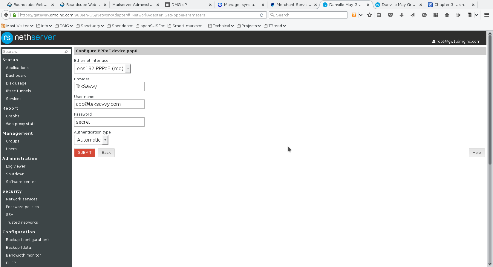
- Screenshot 3
Next fill in a descriptive name, your username and password. You will notice that the password is plainly visible. It is not masked. In TekSavvy’s case, the default of authenticaton type worked just fine.
Once you click SUBMIT, you should find that now it is all working. By default the ethernet interface as well as the ppp0 interface is placed in the RED zone.
My sanity check is to use a terminal session and check it using ifconfig plus netstat outputs. I also ping various internal and external systems.
The NEXT TWO steps are OPTIONAL – only use if you have a /30 (or /29) subnet.
Step 4 – setup optional /30 subnet
When using Nethserver in this manner, the server acts as a gateway for the subnet. This means that the /30 subnet gives two IP addresses (according to networking rules that the first is the network ID and the last is the broadcast).
In this example, there are four numbers:
76.10.177.52 – subnet ID
76.10.177.53 – gateway IP
76.10.177.54 – mail server (or whatever)
76.10.177.55 – broadcast
The subnet mask is then 255.255.255.252
Screenshot 4 shows the configuration for the third ethernet interface. What works best for me is using the ORANGE (DMZ) zone.

- Screenshot 4
Screenshot 5 shows the final configuration of the network interfaces.

- Screenshot 5
Step 5 – setup the firewall
In order to allow access to the server(s) in the ORANGE zone, you must perform two steps with setting up the firewall.
First define an object for your server (or zone). Since in this example, there is only one server, so I selected the Hosts tab on the Firewall Objects page. See screenshot 6.
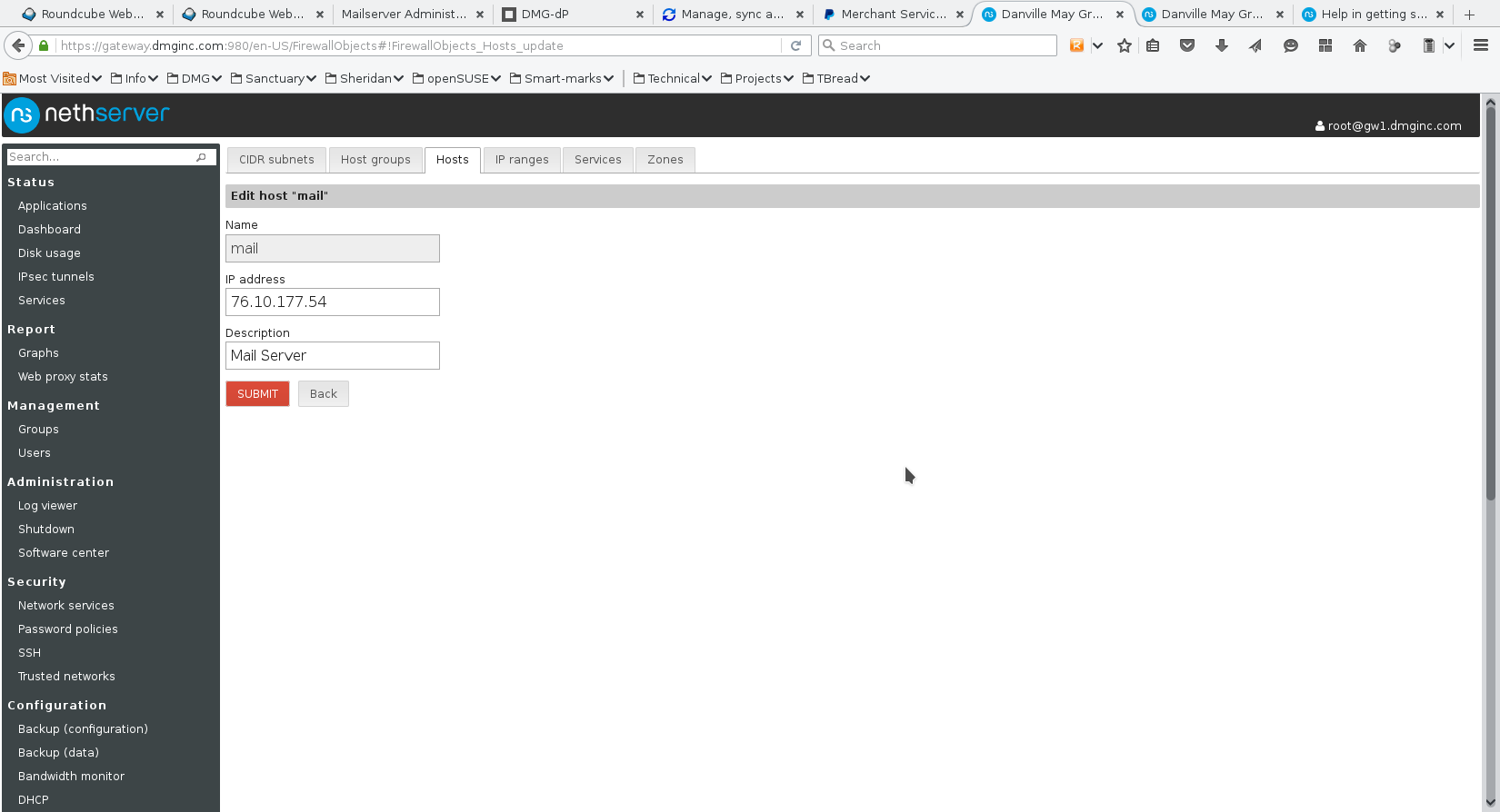
- Screenshot 6
Next on the Firewall rules, you have to add two rules – one to allow traffic to the host object and one to allow traffic from the host object. See screenshots 7 and 8. Screenshot 9 shows the final list of firewall rules. In screenshots 7 & 8, I placed the rules at the start of the firewall. This means that your target host (mail in this example) MUST have its own firewall setup and operational.
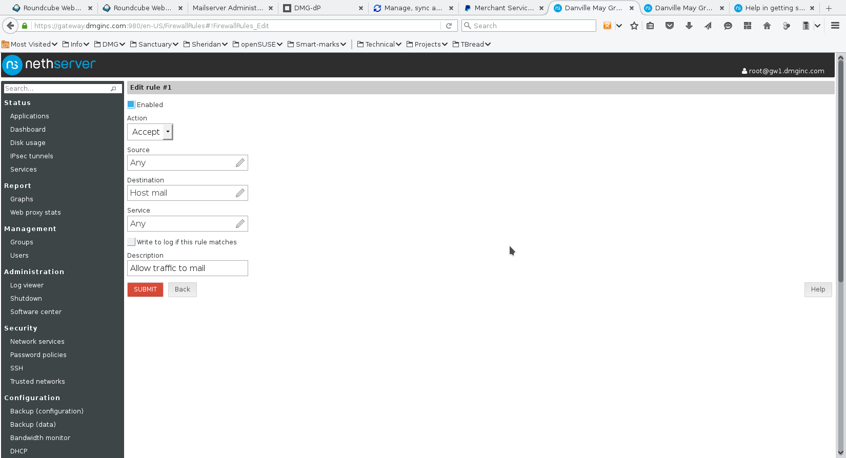
- Screenshot 7

- Screenshot 8

- Screenshot 9